In mechanical construction, an extremely important factor is reading technical drawings. In order to read technical drawings, construction workers must understand all the weld symbols in the drawings. In the following article, we will help you understand more about welding techniques on technical drawings in detail.
What types of welds are there?
In welding technology often include many different types of welds, depending on the needs of use. Currently there are the following types of welds:

 Spot weld or line weld
Technical conventions for welds on drawings
Welding symbols according to Vietnamese standards, the convention and representation of welds on the drawing does not depend on the welding method:
Visible welds are indicated by basic strokes.
Hidden welds are denoted by dashed lines
Points that are visible are denoted by a “+” sign, which is represented by a basic solid line.
For welds specified by the designer it is necessary to have the dimensions of the general structural elements specified on the drawings.
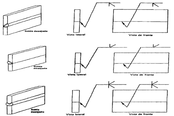
Welds or weld spots are conventionally used with a vertical line and dashed line. This dash is drawn parallel to the runway of the drawing and at the end of the line there is a half arrow pointing to the position of the weld.
Lines and Roman numerals indicate solder layer order.
The representation of a weld or weld point is conventionally using a aligner or dashed line of the aligner.
The limit of the weld is equal to the solid line, and the solid line is used to denote the limit of the structural elements.
Conventional structure for standard weld symbol
The weld parameters are usually provided with additional symbols. Usually, these symbols are placed on or around the weld line.
Welding method symbol, welding type
T: Manual arc welding
A: Automatic welding under the drug layer, no need to use potting pads or pre-attached welding
B: Semi-automatic welding under the potion, without the use of drug pads or pre-welded welding
Bt: Semi-automatic welding under the drug with a steel backing plate
The symbol for the type of weld, if the welding connection is for the auxiliary side, written below the horizontal line, is denoted by the lowercase letters below, accompanied by numbers to indicate the type of welding connection:
m: butt-welded connection.
t: T-welded connection.
g: fillet weld.
c: overlap welding connection.
d: welded joint.
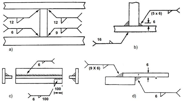
The Delta symbol and the number next to it represent the side height K of the T-weld and fillet welds. Intermittent weld length, symbol “/” or “Z” with digits indicating the welding step.
Secondary symbol


The weld machined surface smoothness may be indicated above or below the horizontal line immediately following the weld type designation. If the weld requires inspection, write below the bevel line.
In case the drawing has the same welds, just write their number and number, this symbol should be written above or below the horizontal line, if there is no space, above the bevel line.
SWISS TECH SCHREINER
Like many great businesses, swiss techs began in a garage. the year was 1990, and lothar schreiner had decided to take his decade of experience in the food processing industry and strike out on his own. with a commitment to hard work, honesty and customer service, swiss tech s. has steadily grown and is currently the largest employer of sanitary welders in west germany. in order to offer its customers in the food, beverage, and pharmaceutical industries a complete range of coverage the company supports a large staff including mobile crews, project managers, engineers, and administrative support.
What types of welds are there?
In welding technology often include many different types of welds, depending on the needs of use. Currently there are the following types of welds:
- Square groove weld
- Groove weld –V – single
- Groove weld – V – double
- Single chamfer weld
- Double chamfer weld
- Groove weld – U – single
- Groove weld – U – double
- Groove weld – J – single
- Groove weld – J – double
- One side fillet weld
- Side weld
- Groove weld VO
- The solder joint breaks the hour
- Button weld

Technical conventions for welds on drawings
Welding symbols according to Vietnamese standards, the convention and representation of welds on the drawing does not depend on the welding method:
Visible welds are indicated by basic strokes.
Hidden welds are denoted by dashed lines
Points that are visible are denoted by a “+” sign, which is represented by a basic solid line.
For welds specified by the designer it is necessary to have the dimensions of the general structural elements specified on the drawings.
Welds or weld spots are conventionally used with a vertical line and dashed line. This dash is drawn parallel to the runway of the drawing and at the end of the line there is a half arrow pointing to the position of the weld.
Lines and Roman numerals indicate solder layer order.
The representation of a weld or weld point is conventionally using a aligner or dashed line of the aligner.
The limit of the weld is equal to the solid line, and the solid line is used to denote the limit of the structural elements.
Conventional structure for standard weld symbol
The weld parameters are usually provided with additional symbols. Usually, these symbols are placed on or around the weld line.
Welding method symbol, welding type
T: Manual arc welding
A: Automatic welding under the drug layer, no need to use potting pads or pre-attached welding
B: Semi-automatic welding under the potion, without the use of drug pads or pre-welded welding
Bt: Semi-automatic welding under the drug with a steel backing plate
The symbol for the type of weld, if the welding connection is for the auxiliary side, written below the horizontal line, is denoted by the lowercase letters below, accompanied by numbers to indicate the type of welding connection:
m: butt-welded connection.
t: T-welded connection.
g: fillet weld.
c: overlap welding connection.
d: welded joint.
The Delta symbol and the number next to it represent the side height K of the T-weld and fillet welds. Intermittent weld length, symbol “/” or “Z” with digits indicating the welding step.
Secondary symbol

The weld machined surface smoothness may be indicated above or below the horizontal line immediately following the weld type designation. If the weld requires inspection, write below the bevel line.
In case the drawing has the same welds, just write their number and number, this symbol should be written above or below the horizontal line, if there is no space, above the bevel line.
SWISS TECH SCHREINER
Like many great businesses, swiss techs began in a garage. the year was 1990, and lothar schreiner had decided to take his decade of experience in the food processing industry and strike out on his own. with a commitment to hard work, honesty and customer service, swiss tech s. has steadily grown and is currently the largest employer of sanitary welders in west germany. in order to offer its customers in the food, beverage, and pharmaceutical industries a complete range of coverage the company supports a large staff including mobile crews, project managers, engineers, and administrative support.

